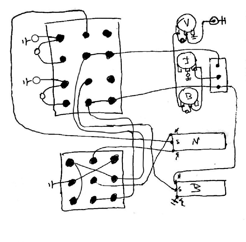
Can anyone detect problems off-hand? Capacitors are circles and no numbers so it remains un-cluttered for wiring purposes
-Just noticed the '08/25/80' schematic phase 3pdt has a different layout than the '1991' schematic. Does this make a difference? (I think it doesn't based on the routing of the crossover wires, anyone feel differently? I already knew the '08/25/80' schematic has different treble pot/bridge switch routing, and that's visible below in the originals)
-There's also some either contradictions or else simplifications in the pickup routing shown on the bottom-left of the earlier schematic; they omit the switch among other things, but also doesn't seem consistent with the 'split' rhythm wire, so I guessed at the correct placement based on the other schematic. Or I just have it wrong
-I had trouble figuring out the arrangement of the four capacitors on the 4pdt from the 1991 schematic; it's a guess based on the '08/25/80' schematic as a result.
At some point I want to wire another of my HH guitars the same as an F100 so this is my homework

The originals: