The place to discuss, post photos, video, and audio of the G&L products (US instruments, stomp boxes, etc.) produced after 1991, including the amps & gear we use with them.
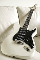
Just cracked open my S-500 to swap out the pickups for some non-MFD's. The stock configuration was 1 MFD in the neck, 1 MFD in the middle, 1 Seymour Duncan TB-4 in the bridge. I want to keep the same configuration, just swap the pups, but I'm confused by the wiring.
What I don't understand is that it appears the neck and middle pickup ground wires are going to the switch (see picture), while the live wires are being grounded on the second (treble) pot. Is this correct? I was under the impression that the neck wires were black/ground, white/live and the middle wires were green/ground, yellow/live. If that is indeed the case then it means that the neck & middle pickup wiring is reversed. Can someone help me understand?
I just want to make sure that I install the new pups correctly... thanks!
For the MFD's, the 'hots' do appear to be going to ground and the black ground wires to 'hot' on the selector switch. My basic understanding of electronics says that it won't matter for a DC inductance device like a pickup, as long as the ground leads consistently go to 'hot' and vice versa.
I suspect the MFD's are wired 'wrong way round' to render them in phase with the Duncan humbucker. When I've installed SD pickups in the past I've been left scratching my head as their wiring convention seems to be the opposite of everybody else's!
Someone more knowledgeable than me will be along soon enough I'm sure.........
Thanks for the input. Is there any way to tell if the pickups are in or out of phase without "fully" installing them and stringing up the guitar? Can I just tap on the pole pieces or something and compare volume levels or some kind of similar trick so that I don't end up wiring it up wrong and putting the entire guitar back together only to find out I have to take it apart again and toss a set of string.
And to answer your question, I bought a set of Porter Pickups (porterpickups.com). The neck and middle are a 1960's strat set, while the bridge is a Porter Classic humbucker. The wiring on the neck/middle pickup is simple 2-wire (black/white). The wiring on the humbucker is fairly standard 4-way (white/red/black/green).
I'm still questioning whether or not I need to reverse the phase for the neck/middle pickup. It seems the Duncan TB-4 'bucker wiring is fairly standard and the G&L MFD's were standard, yet they were in reverse phase with the humbucker. Does this mean I should install the Porter's the same way?
Connect a multimeter to each of the pickup. Put it to some low range for Volt or Ampere and DC. Approach some piece of iron, e.g. a screwdriver, quickly to the poles or pull it off. You'll see some reaction on the multimeter which goes either to plus or to minus depending on your movement. So that shows the electric orientation of the pickup.
If all the new pickups are Porters then they should be in phase with each other if you apply the same conventions to each pickup when you hook them up. e.g. all black wires go to ground, all whites to hot.
It tends to get complex only when pickups from different manufacturers are combined.
This looks interesting. I find the bridge pu of the S500 the least desirable. Putting a HB there will help with those High gain / Distortion sounds.
Single coil tends to feedback with High Gain. You can change the tone to cut off high frequencies and it will remove it. Good luck, tell us how it goes.
What pickguard are you using to handle the HB?
When you say you just want to replace the pup, do you want the option of all 3 ON at once?
Philby wrote:If all the new pickups are Porters then they should be in phase with each other if you apply the same conventions to each pickup when you hook them up. e.g. all black wires go to ground, all whites to hot.
It depends. And as shown in the first post of this thread, it's not true for the S-500 and also as I've seen, mostly for all Strat type sets. The middle pickup has to be wired inverse, as it's build inverse magnetically. To "correct" that for a string producing an amplitude, it has to be wired inverse. This will affect only the positions where more than the middle pickup is involved. If done properly, it will affect the "in between" positions to be hum bucking, if it's done wrong these positions will be out of phase.
I think you're getting confused between electrical phase and magnetic polarity. One is affected by how the hot and ground wires are wired with respect to each other. Get this one wrong and you get thin out of phase sounds when 2 pickups are used together.
The other depends on the orientation of the magnetic fields in each pickup with respect to each other. Get this wrong and, if you're lucky, you get hum cancelling when 2 pickups are used together.
Miles Smiles wrote:And the reason is quite obvious.
Could you elaborate Miles?
OK, you wind 3 Strat-type pickups the exactly same way and you put a white wire on the start of the coil winding and a black one on the end. Now you insert the magnets. For one of the three pickups you decide to put the north pole of the magnets to the bottom instead on the top.
This pickup is than taken as the middle pickup. Now you have to wire that pickup with the black wire to the switch and the two other ones have to be wired with the white side to the switch. The remaining wires go to ground. Now you have hum bucking features in both in between modes (out of phase for hum) and no mode is out of phase for what is inducted by the strings.
Because reversed polarity of the magnets needs reversed polarity of the coil, to produce the same electric current (same phase) as a non reversed pickup.
Thanks Miles. I get the RWRP thing. The pickup sets I've installed in the past (mainly G&L and Fender) have phase consistent colour coding of the wires (e.g. black to gnd, colours to hot), even for the RWRP middle pickup.
Are you saying that some manufacturers reverse the colour convention for the middle pickup? Even though it's electrically consistent I think that scenario would make my head explode.
Someone here posted 3 different S500 diagrams...I think.
And this is how I obtained this pic.
Version 2 is what I have, I did not get the other versions because it would only confuse me more.
Hello everyone first post! I just happened to get a steal on an s500 tribute because it wasn't working right. I discovered the culprit is the black wire that is soldered to the spring claw has severed from its original location on one of the pots. I can't tell what pot it was originally soldered to, but the picture diagram in this thread shows it being soldered to the bass cut pot. I can tell with great certainty that on this particular guitar I have the black wire was not soldered to the bass pot, but one of the other two. My question is: Does it matter which pot its soldered to? It looks like each of the pots are jumped by black wires so in my mind it shouldn't make a difference which pot it's soldered to. Is this correct thinking?
Roadhouse wrote: It looks like each of the pots are jumped by black wires so in my mind it shouldn't make a difference which pot it's soldered to. Is this correct thinking?
Yes, as long no ground loops are created,that should be fine. ( The diagram meowmix posted shows it soldered to the treble-cut )
While it is good practice in electronics to generally avoid any (ground) conductor loops it's actually completely irrelevant in electric guitar wiring. You'd need a truly horrible (read: almost lethal) magnetic field strength to induce a signal of any significance, at that field strenght your pickups would pick up much more hum, even when humbucking.
Actually, so called ring or grid grounding (distributed grounding) is the preferred method, multiple ground paths help reduce chance of malfunction, when one ground connection becomes invalid there's still others keeping the circuit operational.