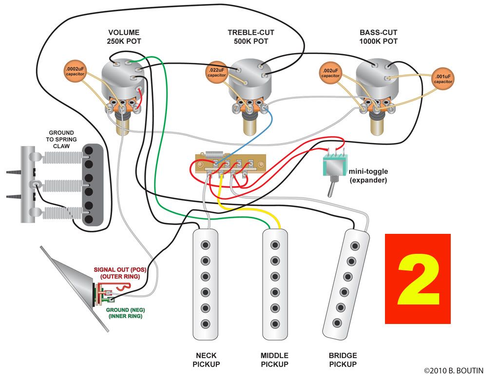
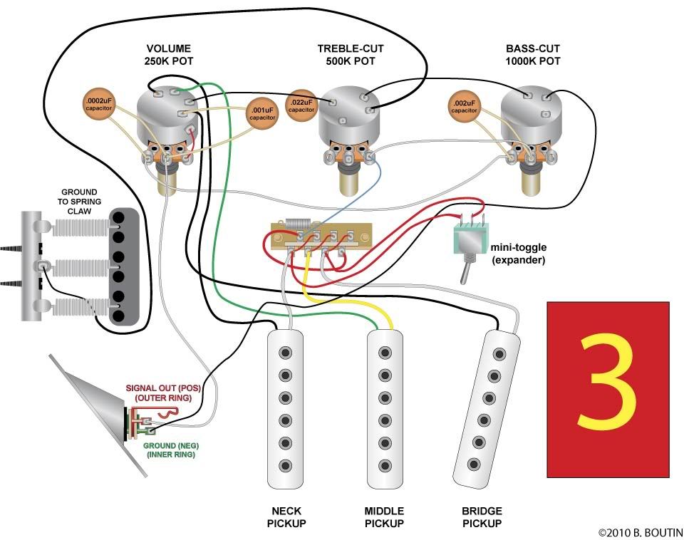
help with S-500 wiring

The place to discuss, post photos, video, and audio of the G&L products (US instruments, stomp boxes, etc.) produced after 1991, including the amps & gear we use with them.
burndog
Posts: 15
Joined: Sat Nov 20, 2010 7:47 am

help with S-500 wiring

Post by burndog »

Hi, I bought a used S-500 that had had it's wiring changed to a typical strat style ( the guy did a poor job ) anyway, I want to bring it back to original, and have ordered all new pots and switches so I can start clean. In trying to locate an easy to read wiring diagram I had no luck. The guitar, I was told is from about 1996 or 97.

The diagrams here really don't tell me much, but I noticed the Legacy has a very similar diagram that is clearer. For the wiring for the 5 way switch I found another diagram. In short, I have pieced together from a few different things I found, and would love it if someone who understands circuits can tell me if I have everything right. I have drawn up a diagram to the best of my knowledge.

Can someone let me know if this is correct. Please note the cap values as I am new to this and have tried my best using what I have learned about deciphering what is stamped on caps ( and like I said, I got my info from several different sources on the internet.)
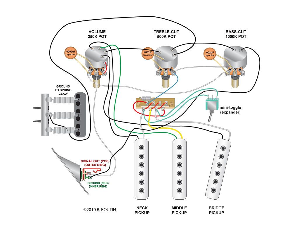
Image


well I guess photobucket has a size restriction...I could email a high res image if you wanted to print it...it would be much clearer.
User avatar
Philby
Posts: 743
Joined: Mon Sep 27, 2010 3:30 pm
Location: Melbourne, Australia

Re: help with S-500 wiring

Post by Philby »

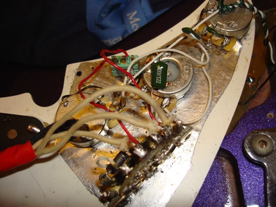
I've been going through the same process. My S-500 (the one in my avatar) had the original MFD pickups installed in a Legacy pickguard with Legacy wiring. I contacted the guy I bought it from who kindly e-mailed me a photo of the original S-500 wiring which he had installed in another guitar. I don't know if this will help you.....

Image

Your wiring diagram looks correct, except for a missing 2nd capacitor on the bass pot. This 2nd cap is not installed on Legacy's, only S-500's. I believe its function is to reduce noise/interference. I've yet to install it on my guitar but will do it the next time I change strings. My S-500 is quite noisy so hopefully the cap will help.

By the way, if you don't want the hassle of drilling a hole for the mini-toggle you can install a DPDT push/pull pot to get the extra pickup combinations. That's what I ended up doing and it works a treat.

HTH, Phil.
burndog
Posts: 15
Joined: Sat Nov 20, 2010 7:47 am

Re: help with S-500 wiring

Post by burndog »

thanks phibly, much appreciated. I was not sure about the 2nd cap on the bass pot. I have seen one wiring diagram with, and one without, and on one post a person figured the second cap would make for a permanent treble cut. I will likely add it temporarily with aligator clips to see what the difference is.

Your photo was indeed helpful...I see the mini-toggle should be wired in the center and to one of the outside posts...I checked the switch for continuity and sure enough, I had it wrong.

Image


Here is a new and improved version, can anyone see any mistakes with this set up?
User avatar
Philby
Posts: 743
Joined: Mon Sep 27, 2010 3:30 pm
Location: Melbourne, Australia

Re: help with S-500 wiring

Post by Philby »

Please let us know what the effect is of the 2nd cap on the bass pot when you try it!

I haven't wired mine in yet. I'll wait to hear a report first.
burndog
Posts: 15
Joined: Sat Nov 20, 2010 7:47 am

Re: help with S-500 wiring

Post by burndog »

I will philby, but I have to say that I am even more confused now. The diagram from the G&L site that does show the second cap looks like it goes on the treble cut control http://www.glguitars.com/schematics/S-5 ... iagram.pdf

yet your photo shows it goes on what I expect is the bass cut (farthest away from the volume) at least according to this link also from the G&L site...http://www.glguitars.com/schematics/s50 ... tching.pdf

and of course there is this link from the G&L site that does not show the extra cap at all ( nor does it even show the mini-toggle or where the signal from the pup selector switch enters the rest of the circuit)...http://www.glguitars.com/schematics/S-5 ... rawing.pdf.

I really am surprised that a company as large as G&L does not have better support at least in the wiring diagrams...the early s-500 diagram is not very good at all, plus it is not easy to determine what is early and what is late

Now I assume my S-500 is of the early type since it does have one pickup with green and yellow wires.

I am hopeing that someone who is changing strings can pop off their pickguard and compare their proper wiring to my diagram and let me know what innacuracies I have.
burndog
Posts: 15
Joined: Sat Nov 20, 2010 7:47 am

Re: help with S-500 wiring

Post by burndog »

Ok, so this one should be a touch more accurate, or at least I am hoping


If anyone with an S-500 is changing strings, I would be oh so grateful, if they could pop off their pickguard and compare the wiring setup including cap values to my diagram, and let me know where I have gone wrong.

Image
User avatar
Craig
Site Admin
Posts: 11349
Joined: Tue Mar 03, 2009 10:52 am
Location: Either Coto De Caza, CA or Paso Robles, CA

Re: help with S-500 wiring

Post by Craig »

I posted some new photos in the Instrument Manuals and Wiring Schematics Album in the Gallery today.

Here's the one for the S-500:
Image

Hope this helps.
--Craig [co-webmaster of guitarsbyleo.com, since Oct. 16, 2000]
Welcome! Read This First
Got a G&L question? Check out the: G&L Knowledgebase
Current G&L Specifications and Options
burndog
Posts: 15
Joined: Sat Nov 20, 2010 7:47 am

Re: help with S-500 wiring

Post by burndog »

awesome craig...very much appreciated:)
zedsnotdead
Posts: 41
Joined: Wed Sep 01, 2010 7:10 pm

Re: help with S-500 wiring

Post by zedsnotdead »

Hi!!!

I just came across this thread, i know it's an old thread and I am sorry.

it just happens that my tribby S-500 doesn't have the 0,001uF capacitor on the Bass pot - the one that shunts the 5way output to ground (yes, the 5way output connects also to the right lug on the treble pot, but they are all shunted like on the same spot.

if we check the wiring diagram, this 0,001uF cap is in parallel to the 500K + 0,022uF.
So mathematically speaking, this circuit is equivalent to 500K pot and (0,001+0,022)uF in series.
Thus, equivalent to 500K variable resistor in series with a 0,023 capacitor.

The difference between a 0,022 and a 0,023 capacitor is so negligible that really i dont understand why G&L even bother with this 0,001uF cap.

Am I missing something here??
MaxBoogie
Posts: 1
Joined: Sat Dec 08, 2012 5:59 pm

Re: help with S-500 wiring

Post by MaxBoogie »

Okay, so I'm a little late to this party... But your diagram 2 is correct, not diagram 3... at least as I stare at my '96 S-500 electronics. I own 3 S-500's and they are all like diagram 2. Apologies if this has been answered elsewhere...
lakesidepark
Posts: 1
Joined: Mon Nov 05, 2018 10:19 am

Re: help with S-500 wiring

Post by lakesidepark »

One doubt, I'm rewiring my S500 cause I have one fail potentiometer, does anybody know the function of 1nF capacitor???

It is high peak cut?

Thanks