F-100E Wiring diagram and pictures of the circuit
Tue Apr 26, 2011 10:16 am
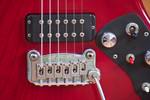
Today I've made a wiring diagram and some pictures of my 1982s F-100E electric circuit. The pictures are detailed enough to identify every part used in the circuit, even in the electronic board with the OP-Amp and the path on that board.
It started, when I again played with the active circuit settings of that guitar and again was unsatisfied with the sound in active mode. It just lets me think about a noise gate which closes to early. On an older picture of the circuit, I recognized the chip on the boost board to sit in a socket. So I opened control cavity, pulled out the chip, put a little bit of Tuner600 into the socket and moved the NTE944M several times in and out. But that didn't change much for the distorted sound.
But when I tried a clean sound, I noticed everything is working as it should, or at least it doesn't show that gate like behaviour, but when switched to active the sound is louder but more dull, than in passive mode. It's a lot brighter though in treble boost mode, maybe it's like it had been thought to be. But maybe there's something to be changed on the board. A worn out capacitor? Does anybody have a clue?
But as it had been opened, I began to document the electrics, as there's nothing like that available elsewhere for the F-100E. So now there they are and I've loaded everything in an album in the gallery on the board server, but the pictures were converted to an unusable size (no details). So below there's a's list of links to the full sized diagram and pictures and may be copied by Craig to the right place in the gallery, only if it's thought to be useful, of course.
Diagram:
http://dl.dropbox.com/u/5322859/Wirings ... iagram.png
Pictures:
http://dl.dropbox.com/u/5322859/Wirings ... G_4013.jpg
http://dl.dropbox.com/u/5322859/Wirings ... G_4016.jpg
http://dl.dropbox.com/u/5322859/Wirings ... G_4017.jpg
http://dl.dropbox.com/u/5322859/Wirings ... G_4021.jpg
http://dl.dropbox.com/u/5322859/Wirings ... G_4022.jpg
http://dl.dropbox.com/u/5322859/Wirings ... G_4026.jpg
http://dl.dropbox.com/u/5322859/Wirings ... G_4030.jpg
http://dl.dropbox.com/u/5322859/Wirings ... G_4032.jpg
http://dl.dropbox.com/u/5322859/Wirings ... G_4033.jpg
http://dl.dropbox.com/u/5322859/Wirings ... G_4034.jpg
http://dl.dropbox.com/u/5322859/Wirings ... G_4035.jpg
http://dl.dropbox.com/u/5322859/Wirings ... G_4038.jpg
http://dl.dropbox.com/u/5322859/Wirings ... G_4042.jpg
http://dl.dropbox.com/u/5322859/Wirings ... G_4043.jpg
http://dl.dropbox.com/u/5322859/Wirings ... G_4045.jpg
http://dl.dropbox.com/u/5322859/Wirings ... G_4046.jpg
http://dl.dropbox.com/u/5322859/Wirings ... G_4047.jpg
http://dl.dropbox.com/u/5322859/Wirings ... G_4049.jpg
http://dl.dropbox.com/u/5322859/Wirings ... G_4056.jpg
Last edited by Miles Smiles on Tue Apr 26, 2011 11:37 am, edited 1 time in total.
Re: F-100E Wiring diagram and pictures of the circuit
Tue Apr 26, 2011 10:52 am
Miles Smiles wrote:as there's nothing like that available elsewhere for the F-100E.
Oops, I've found them already there but hidden in the F-100 Album.
http://www.guitarsbyleo.com/GALLERY2/ma ... itemId=349
But somehow interesting, the circuit there is slightly different to that in my guitar. First of all the OP-amp is another one.
Re: F-100E Wiring diagram and pictures of the circuit
Wed Apr 27, 2011 11:16 pm
Miles Smiles wrote:Miles Smiles wrote:as there's nothing like that available elsewhere for the F-100E.
Oops, I've found them already there but hidden in the F-100 Album.
http://www.guitarsbyleo.com/GALLERY2/ma ... itemId=349
But somehow interesting, the circuit there is slightly different to that in my guitar. First of all the OP-amp is another one.
I will see if I can find out how many sources of the OP-AMP they used and if anyone knows what would cause the tone problem
when active.
When I get some time, I will added your photos to the F-100 Wiring Schematics and Picture Diagrams Album in the Gallery.
Thanks for sharing them.
Re: F-100E Wiring diagram and pictures of the circuit
Thu Apr 28, 2011 11:18 pm
Craig wrote:I will see if I can find out how many sources of the OP-AMP they used and if anyone knows what would cause the tone problem
when active.
Thanks! In the meantime, I've noticed, that I get a very similar tone in active mode, when I completely roll off the bass control on the guitar. So what's happening is, that there's a bass boost, but the user manual says it will boost not anything in the middle position of that switch.
In the circuit of my guitar, the treble control has no effect on the bridge pick-up, as there's just one line from the input for the neck pick-up on the 3-way selector switch to the tone control. In the other drawing there's a line from the output of the selector to the tone control.
The other big difference are that two capacitors which are on the splitter switch, which aren't in the drawing of Gabe Dellevigne. But instead there's a second capacitor on the bass control, which is not in mine.
If you can find out, why these differences are, it would be great.
Some pictures of that guitar: http://i.wuell.net/gallery/view_album.p ... Name=F100E
Re: F-100E Wiring diagram and pictures of the circuit
Fri May 06, 2011 3:43 pm
push
Re: F-100E Wiring diagram and pictures of the circuit
Fri May 06, 2011 8:11 pm
Miles Smiles wrote:push
I have not heard back from my contacts at G&L. It's quite possible we may not get the history you are seeking.
Stay tuned (no need to push or bump).
Re: F-100E Wiring diagram and pictures of the circuit
Sat May 07, 2011 12:00 am
OK, thanks so far. 