G-200 Wiring Schematic
Fri Apr 14, 2017 11:01 am
I'm looking for the G-200 wiring schematic. Does anyone have one or a link to one?
Much thanks in advance,
Tom
Much thanks in advance,
Tom
Re: G-200 Wiring Schematic
Sat Apr 15, 2017 9:21 am
FZTNT wrote:I'm looking for the G-200 wiring schematic. Does anyone have one or a link to one?
Much thanks in advance,
Tom
Tom,
I do not see one in the Gallery nor do I have one as such but I hope these will be a good start:
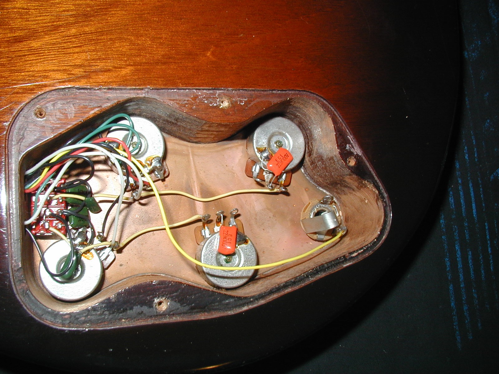
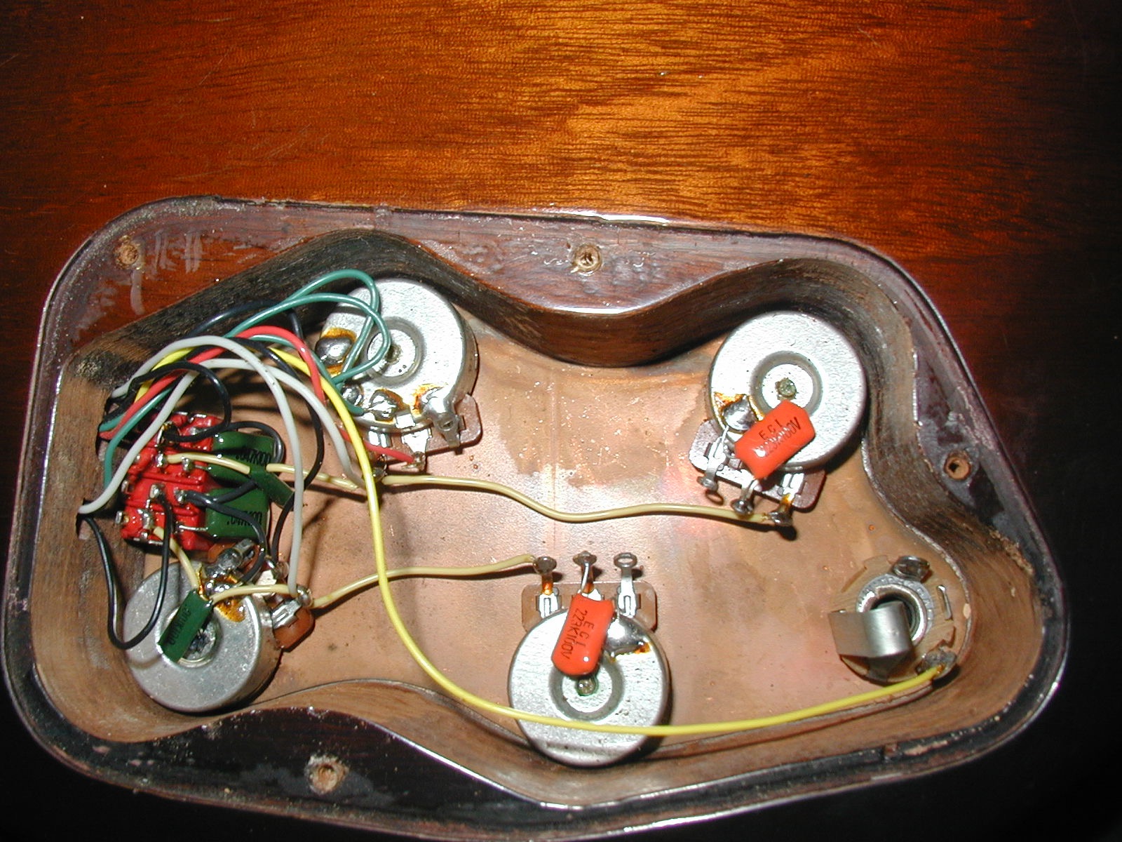
- Jos
Last edited by yowhatsshakin on Mon Nov 11, 2019 3:24 am, edited 1 time in total.
Re: G-200 Wiring Schematic
Sat Apr 15, 2017 9:34 am
That's some good reference...thanks Jos.
Maybe this thread will crystallize an answer to the 'G-200 mod' quest.
I bet someone here could draw up some schematics .
Is there any resistance in the ground plate?Would that have an effect on tone?
I notice there is no negative lead on the jack
Maybe this thread will crystallize an answer to the 'G-200 mod' quest.
I bet someone here could draw up some schematics .
Is there any resistance in the ground plate?Would that have an effect on tone?
I notice there is no negative lead on the jack
Re: G-200 Wiring Schematic
Sat Apr 15, 2017 11:44 am
Elwood wrote:That's some good reference...thanks Jos.
Maybe this thread will crystallize an answer to the 'G-200 mod' quest.
I bet someone here could draw up some schematics .
Is there any resistance in the ground plate?Would that have an effect on tone?
I notice there is no negative lead on the jack
I noticed that as well Elwood. There are a lot of wires in there and caps as well.
Thanks Jos this will at least be a good start and like Elwood said, perhaps someone has a schematic to share.
Tom
Re: G-200 Wiring Schematic
Sun Apr 16, 2017 1:00 pm
Elwood wrote:I notice there is no negative lead on the jack
I think no wire is needed because the ground plate is the single connection tying all the grounded housings and ground on the output jack together, in this way avoiding ground loops by having additional connections.
- Jos
Re: G-200 Wiring Schematic
Mon Apr 17, 2017 11:11 am
My neg on the jack is connected to the brass grounding plate right under the jack. It did come off while messing around with the control plate and did not seem to make much difference if any.
I seem to be having level differences between the pickups depending on where the red mini switch is set at. What are the three functions of that switch supposed to be? Is there a setting that does nothing, a coil split with boost and split without boost?
Thanks,
Tom
Still would love to see a schematic if someone has one to share.
Re: G-200 Wiring Schematic
Mon Apr 17, 2017 11:38 am
FZTNT wrote:I seem to be having level differences between the pickups depending on where the red mini switch is set at. What are the three functions of that switch supposed to be? Is there a setting that does nothing, a coil split with boost and split without boost?
For the functioning of that red-tip switch, see my write-up here. There's a picture of an original spec sheet with instructions in the lower right corner of that page.
Hope this helps,
- Jos
Re: G-200 Wiring Schematic
Fri Apr 21, 2017 10:50 am
Thanks Jos, I will have to run it through all the different switch positions once I get it put back together. I think I have the wiring correct. There's a lot of wires and caps crammed into that small space. I still notice some diminished levels depending on switch positions and pickups selected but maybe with strings it will be better. All I can do now is tap with a tweaker and I do get unexpected results.
How do you test to see if the caps are bad?
On the same guitar, it really could use a Re-fret. Will that affect the value much? It is 36 years old and has been played but not abused. Just wondering, I am sure I will get it done when I find someone I am comfortable with doing it. What was the fret wire they used on these back then?
Tom
Re: G-200 Wiring Schematic
Thu Jun 15, 2017 1:45 pm
Thank you for the photos Jos. Pot Values and Cap Values would be handy to know. ~Patrick
Re: G-200 Wiring Schematic
Thu Jun 15, 2017 8:14 pm
JagInTheBag wrote:Thank you for the photos Jos. Pot Values and Cap Values would be handy to know. ~Patrick
Perhaps this post, located in the G&L Technical Questions & Tips sub-forum of the G&L Knowledgebase Forum, will help some: GPD comments on the G-200 vs LP.
Re: G-200 Wiring Schematic
Sun Jun 18, 2017 1:18 pm
Craig wrote:JagInTheBag wrote:Thank you for the photos Jos. Pot Values and Cap Values would be handy to know. ~Patrick
Perhaps this post, located in the G&L Technical Questions & Tips sub-forum of the G&L Knowledgebase Forum, will help some: GPD comments on the G-200 vs LP.
I just posted this in the Knowledgebase Forum: Parts to convert F-100 to G-200 wiring.
Hope this helps.
Re: G-200 Wiring Schematic
Sun Jun 18, 2017 9:19 pm
Thanks Craig (and yoeleven) !
Re: G-200 Wiring Schematic
Mon Jun 19, 2017 9:32 am
Sweet! Thank you everyone!